
Page 47 - PEN eBook July 2023
P. 47
Design
B-TRAN DRIVER & DPT
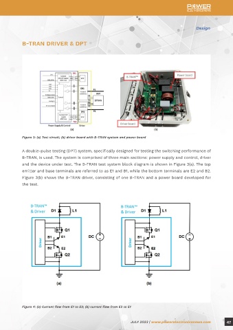
Figure 3: (a) Test circuit; (b) driver board with B-TRAN system and power board
A double-pulse testing (DPT) system, specifically designed for testing the switching performance of
B-TRAN, is used. The system is comprised of three main sections: power supply and control, driver
and the device under test. The B-TRAN test system block diagram is shown in Figure 3(a). The top
emitter and base terminals are referred to as E1 and B1, while the bottom terminals are E2 and B2.
Figure 3(b) shows the B-TRAN driver, consisting of one B-TRAN and a power board developed for
the test.
Figure 4: (a) Current flow from E1 to E2; (b) current flow from E2 to E1
JULY 2023 | www.powerelectronicsnews.com 47