
Page 23 - PEN_Ebook_December_2021
P. 23
TEST&MEASUREMENTS Test&Measurements
SELECTING PROGRAMMABLE POWER SUPPLIES
Traditionally, to achieve the best possible output voltage regulation, you would use a linear power
supply. However, linear power supplies tend to be very large, expensive, and highly inefficient at higher
current levels. Recent advances in switching power supply technology make it possible to replace linear
power supplies with switching power supplies in performance applications. Switching power supply
designers face seemingly contradictory goals of low output noise, fast transient response, low cost,
and high density. Achieving low output noise is usually accomplished with multiple stages of filtering
or using larger filter components, both of which lead to higher cost, lower power density, and slower
transient response. More advanced power supplies employ higher switching frequency, better filter
design, and more sophisticated control topologies to optimize all the criteria. When selecting a power
supply for IC test applications, it is essential to examine the voltage transient response specification
and output impedance characteristics to ensure good performance.
OPTIMIZING LOAD WIRING
In many cases, physical constraints force you to position the power supply several feet away from your
IC test board, necessitating at least a few feet of load lead wiring. Load lead wiring impedance can very
quickly degrade the source impedance experienced by the IC. Almost all programmable power supplies
provide sense lead inputs, which allow you to select the point of voltage regulation by connecting the
voltage sense leads at that location. In this application, the sense point would be as close as possible
to the IC. However, the voltage regulation loop can suppress voltage transients at this sense point only
within its control bandwidth. Consequently, a voltage transient can occur at this sense point if the
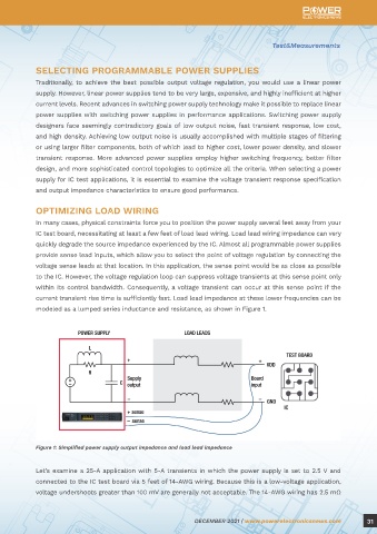
current transient rise time is sufficiently fast. Load lead impedance at these lower frequencies can be
modeled as a lumped series inductance and resistance, as shown in Figure 1.
Supply Clean Power
to Low-Voltage,
High-Current Devices
By Bill Griffith, power solutions manager at Keysight Technologies
Today’s integrated circuits are operating faster than ever. The increased operating speed can lead to
highly dynamic power demand from the power supply, which poses a challenge during testing when
you source power using programmable power supplies. The high-speed current waveforms can lead to Figure 1: Simplified power supply output impedance and load lead impedance
voltage drops at the integrated circuit. If severe enough, the voltage drop can reset the microprocessor
or cause anomalies in your test results. This article explains why the voltage drop occurs, offers several Let’s examine a 25-A application with 5-A transients in which the power supply is set to 2.5 V and
ways to achieve the lowest possible voltage drop by selecting optimal load leads and power supplies, connected to the IC test board via 5 feet of 14-AWG wiring. Because this is a low-voltage application,
and the use of local bypassing. voltage undershoots greater than 100 mV are generally not acceptable. The 14-AWG wiring has 2.5 mΩ
30 DECEMBER 2021 | www.powerelectronicsnews.com DECEMBER 2021 | www.powerelectronicsnews.com 31