Page 16 - PEN eBook July 2022
P. 16

Thermal Management                                                                                                                                                                              Thermal Management


                                                                                                                                   For further improved Z    and
                                                                                                                                                          thja
                                                                                                                                   dynamic power dissipation for
                                                                                                                                   TSC, the implementation of an

                                                                                                                                   intermediate heat spreader is
                                                                                                                                   a good option, as shown in
                                                                                                                                   Figure 7. The thermal capacity
                                                                                                                                   of  this additional heatsink
                                                                                                                                   can store  for a certain  time
                                                                                                                                   (some seconds) the additional
                                                                                                                                   heat  and  transfer  it  further   Figure 7: Single-device heat-spreader mounting
            Figure 5: Standard positive package standoff (left) and negative package standoff (right). The copper pad below the
            package body is beneficial as mechanical support of well-defined height and high board-level reliability in case of a   to  the common heatsink
            negative standoff                                                                                                      and ambience. Depending on the system design, removing the common heatsink and TIM is also
                                                                                                                                   possible for improved system Z   , wherein the heat spreader is the primary heatsink and is directly
                                                                                                                                                                  thja
                                                                               In case of a negative package                       cooled by the fan airflow.
                                                                               standoff (Figure 5, right), other
                                                                               considerations are needed for
                                                                               the PCB design to avoid system
                                                                               reliability issues, which could
                                                                               cause  additional  effort  and

                                                                               complexity  for the  system
                                                                               design and manufacturing.
                                                                               A  negative  package  standoff
                                                                               has the advantage of reduced
                                                                               Z    because of its reduced
                                                                                 thja
                                                                               package    height   tolerance,
                                                                               leading  to  a  thinner  TIM
                                                                               thickness.   However,  when
            Figure 6: Electrical isolation foil and gap filler between the external heatsink   considering  other tolerances
            and the device
                                                                               like PCB  warpage, especially
            with larger PCB size and multiple power devices using a common heatsink, the thermal advantage
            of a negative package standoff becomes less important.                                                                 Figure 8: Typical transient thermal impedance junction ambient (Z thja ) for multiple packages at forced convection


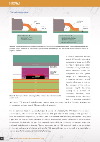
            For the common heatsink approach, Figure 6 shows schematically the TIM stack between device
            and  heatsink,  which  consists  of  insulation  foil  and  gap  filler  in  this  example.  The  gap  filler  is      Thermal performance
            used for compensating device-, heatsink-, and PCB-related manufacturing tolerances. Using only                         Figure  8  shows  Z    time-dependent  plots  for  selected  through-hole  device  (THD),  BSC  SMD,
                                                                                                                                                     thja
            a gap filler for heat transfer, a reliable insulation between the device and external heatsink must                    and TSC SMD packages considering an FR4-based PCB design with forced air cooling. The same
            be ensured. Additionally, the gap filler material must fulfill the necessary breakdown rating, and                     device inside all shown packages is assumed just as the same power losses. Comparing DDPAK
            enclosed particles within the gap filler or blowholes during PCB assembly need to be prevented.                        (TSC package) with TO263 (BSC package) on an FR4-based PCB, DDPAK achieves 60% lower Z          ,
                                                                                                                                                                                                                                 thja
            In general, a clean manufacturing ambient for PCB assembly can lower the risk of system failures                       although the effective cooling area of both packages is quite similar. DDPAK bypasses the bottleneck
            caused by pollution during system manufacturing.                                                                       “thermal vias,” as described in the section before. The graph also illustrates that top-side packages


  16        JULY 2022 | www.powerelectronicsnews.com                                                                                                                                       JULY 2022 | www.powerelectronicsnews.com         17
   11   12   13   14   15   16   17   18   19   20   21