
Page 26 - Power Electronics News - December 2020
P. 26
Smart Energy Smart Energy
age range must be carefully considered due to ture sensors provide multiple benefits, including As an example, once a fault is detected, an ac-
tolerances and abnormal transient voltages that identification of fault locations and causes to tuator like the three-phase relay shown in Fig. 5
cumulate to the maximum operating voltage. 28- support quicker restoration efforts and proactive can automatically break the power line.
V, 36-V, 42-V, or 60-V input power management actions to avoid future unplanned outages. An
solutions are available on the market today. With intelligent sensor provides fault detection, cap-
a margin of only 4 V, 28 V is too close to 24 V to tures key power quality data for day-to-day grid SENSOR SYSTEM
provide a reliable margin for most applications. management, and supports renewable energy Sensors may be located anywhere on the field.
Many standards require 60-V tolerance, eliminat- integration with the ability to detect and report The sensor “box” includes a front-end transceiver
ingg the need to make a choice. It is tempting for on reverse power flows. that handles data and routes power to a step-
many designers to choose a device with a 36-V down voltage regulator. This delivers the appro-
maximum input. However, using a 36-V input is priate voltage to the ASIC/microcontroller/FPGA,
a high-risk approach for sensors and encoders the sensing element, and communication device.
working on a 24-V rail. Even if transient voltage A smart-grid sensor or overhead powerline sen-
suppressor (TVS) diodes are used for surge pro- sor uses wireless or powerline communication.
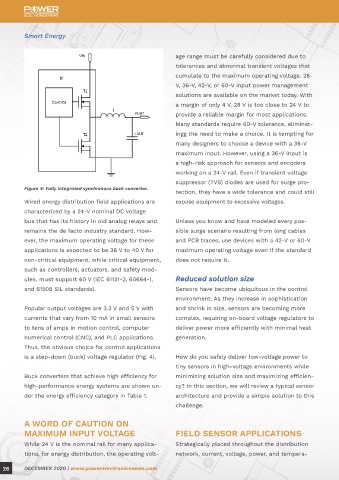
Figure 4: Fully integrated synchronous buck converter.
tection, they have a wide tolerance and could still Fig. 6 shows an overhead sensor in a three-phase
Wired energy distribution field applications are expose equipment to excessive voltages. powerline.
characterized by a 24-V nominal DC voltage
bus that has its history in old analog relays and Unless you know and have modeled every pos-
remains the de facto industry standard. How- sible surge scenario resulting from long cables SAFE LOW-VOLTAGE OPERATION
ever, the maximum operating voltage for these and PCB traces, use devices with a 42-V or 60-V Most sensors are powered by a 24-VDC pow-
applications is expected to be 36 V to 40 V for maximum operating voltage even if the standard er source. However, the field can be a very
non-critical equipment, while critical equipment, does not require it. challenging environment, with long cables and
such as controllers, actuators, and safety mod- strong electromagnetic interference that result
ules, must support 60 V (IEC 61131-2, 60664-1, Reduced solution size in high-voltage transients. Accordingly, the step-
and 61508 SIL standards). Sensors have become ubiquitous in the control down converter inside the sensor must withstand
Figure 5: 2.5-MW three-phase relay.
environment. As they increase in sophistication voltage transients of 42 V or 60 V, which are
Popular output voltages are 3.3 V and 5 V with and shrink in size, sensors are becoming more much higher than the sensor operating voltage.
currents that vary from 10 mA in small sensors complex, requiring on-board voltage regulators to
to tens of amps in motion control, computer deliver power more efficiently with minimal heat As discussed before, for 24-V rails, it is best to
numerical control (CNC), and PLC applications. generation. rely on devices that have an operating maximum
Thus, the obvious choice for control applications of 42 V. According to SELV/PELV/FELV (Safety/
is a step-down (buck) voltage regulator (Fig. 4). How do you safely deliver low-voltage power to Protection/Functional Extra Low Voltage) regula-
tiny sensors in high-voltage environments while tions, an isolated device that handles up to 60 V
Buck converters that achieve high efficiency for minimizing solution size and maximizing efficien- is considered safe to touch. Protection above 60
high-performance energy systems are shown un- cy? In this section, we will review a typical sensor V is provided with the addition of dedicated TVS
der the energy efficiency category in Table 1. architecture and provide a simple solution to this devices.
challenge.
Examples of power solutions that meet the re-
A WORD OF CAUTION ON quirements of building automation sensors are
MAXIMUM INPUT VOLTAGE FIELD SENSOR APPLICATIONS shown in Table 1 under the small size category.
While 24 V is the nominal rail for many applica- Strategically placed throughout the distribution
Figure 6: Smart grid overhead line sensors (Image licensed
tions, for energy distribution, the operating volt- network, current, voltage, power, and tempera- under CC BY-SA).
26 DECEMBER 2020 | www.powerelectronicsnews.com DECEMBER 2020 | www.powerelectronicsnews.com 27