
Page 29 - Power Electronics News - December 2020
P. 29
Smart Energy Smart Energy
However, if strong electromagnetic interference is converters from consideration. Examples of
present, more severe measures are in order. 60-V-rated buck converters are shown in Table 1
under safety and reliability.
A typical sensor power management solution uti-
lizes TVS devices to limit the input voltage (VCC) Increased safety and reliability:
of the front-end buck converter. The associated isolation
input current peaks are reduced by the resistor Isolated DC/DC voltage regulators are found in
RP, a parasitic or physical element in the electric the most diverse applications. Although an iso-
path between the voltage transientsource (V BUS ) lated solution is more complex than a non-iso-
and the sensor. lated one, there is still an expectation for it to fit
in a small space and be highly efficient. In this
Let’s see how to select a TVS out of the LitteI- case study, we will discuss the reasons for isola-
fuse catalog as an example. The general charac- tion in low-voltage power conversion systems.
teristics of a TVS are shown in Fig. 8. Figure 8: TVS V-I characteristics.
According to SELV/FELV regulations, input voltag-
The TVS device is an open circuit until the volt- es below 60 V are considered inherently safe to
age across it reaches V . At this point, it starts touch, but the need for isolation in this operating
BR
to conduct current while its voltage rises slightly range is still pervasive for functional safety and
up to its maximum clamping voltage, V , which reliability reasons. In this voltage range, the pow-
C
Table 1: Automation Sensors. corresponds to the maximum peak pulse current er supply electronic load, typically a very delicate
The power path of a typical sensor system is allowed, IPP. The product of V × I is the maxi- and expensive microcontroller, needs protection.
PP
C
shown in Fig. 7. mum peak power that the TVS can handle (400 It could readily self-destruct if accidentally ex-
W for this TVS family). For effective protection, posed to high voltage.
If the 24-V bus is clean or has an electric noise the TVS V must be above V CC(MAX) , while V must
C
BR
level below the operating voltage of the front-end be below the switching regulator input voltage Isolation also prevents ground loops, Figure 9: Ideal TVS selection.
switching regulator, no protection is necessary breakdown. which occur when two or more
(no TVS in Fig. 7) and a buck converter with a circuits share a common return
typical max input voltage of 36 V or 42 V is suffi- Our V BUS supply is 24 V +25%, –20%, with 30 V path. Ground loops produce
cient for this sensor design. maximum (V BUS(MAX) ). Ideally, with a 60-V-rated parasitic currents that can
buck converter, a SMAJ33A disrupt the output-voltage
with a minimum VBR of 33 regulation as well as introduce
V can be used (as well as a galvanic corrosion of the con-
clamp voltage VC of 53.3 V, ducting traces. This is a phe-
which is well below 60 V). This nomenon that degrades equip-
gives an operating margin of 3 ment reliability.
V above V BUS(MAX) and 6.7 V below
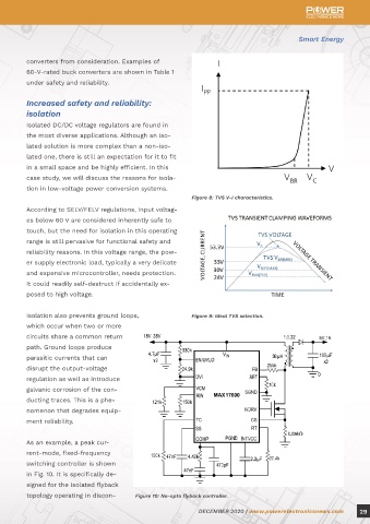
60 V (Fig. 9). As an example, a peak cur-
rent-mode, fixed-frequency
The fact that the buck con- switching controller is shown
verter must withstand 24 VDC in Fig. 10. It is specifically de-
and at least a 53.3-V transient signed for the isolated flyback
Figure 7: Sensor power system. removes a large group of buck topology operating in discon- Figure 10: No-opto flyback controller.
28 DECEMBER 2020 | www.powerelectronicsnews.com DECEMBER 2020 | www.powerelectronicsnews.com 29