
Page 21 - EE Times Europe November 2021 final
P. 21
EE|Times EUROPE 21
PARTNER CONTENT
Silicon Carbide Modules Unlock Higher Power
Density in Motor Drives
By Matthew Feurtado, Applications and Systems Engineer, and Daniel Martin, Senior Manager of Applications
Engineering, Wolfspeed
The traction drive is where nearly all of an electric vehicle’s energy is put to use.
This paper presents a three-phase dual inverter reference design from Wolfspeed
and reveals how its components, including the CAB450M12XM3 power module and
CGD12HBXMP gate driver, along with other key technologies, come together in a
solution designed to enable next-generation EV traction.
he traction drive system of an In designing the system, five key points POWER MODULE PLATFORM
electric vehicle must perform with needed to be considered: OF CHOICE: XM3
the highest possible efficiency while 1. The high power density achievable from A power module based on Wolfspeed’s XM3
T occupying the smallest possible space the use of SiC technology. Although SiC full-SiC platform was the obvious choice
with the lowest weight — all to maximize enables higher temperature operation, because of its exceptional power density. Its
the EV range. With the use of dual drives the high power density enabled requires weight and volume are about half as much
to enhance traction as well as an 800-V that advanced heat-dissipation technolo- as the standard 62-mm module, and the
architecture to reduce losses, the industry gies be used. difference is even more dramatic against an
needs inverters that increase output power 2. The fast switching speeds make the sys- EconoDUAL (Figure 2). The XM3 platform
from smaller size to deliver power density tem more prone to overshoot and ringing is designed using an overlapping planar
well beyond the capability of silicon-based caused by stray inductance; thus, stray structure to achieve low stray inductance.
technologies like IGBTs. The latest gener- inductance needs to be lowered from the The current loops within the module are wide
ation of Wolfspeed’s silicon carbide power busbar structure. and low-profile and yield even distribution
modules are designed to meet these demands 3. This concern also demands low- between the devices, resulting in equivalent
with lower losses, higher power density, and inductance, high-ripple rating capac- impedances across a switch position. The
smaller size. itance while keeping an eye on size power terminals on the module are also
reduction. vertically offset. This enables design of simple
A SYSTEM OVERVIEW 4. The gate driver circuit must have busing between the DC-link capacitors and
The CRD600DA12E-XM3 comprises two banks adequate drive strength to sustain the the module to be laminated all the way up to
of CAB450M12XM3 power modules, each with switching speeds demanded and enabled the module. The end result is a power-loop
CGD12HBXMP gate drivers (Figure 1). The by SiC technology. stray inductance of just 6.7 nH at 10 MHz.
overall objective is to maximize performance 5. The overall power density should be The module features half the stray induc-
through a high-ampacity, low-inductance significantly high to meet end- tance of industry-standard modules and
design that is also low in cost and complexity. application requirements. less than half the volume in a 53 × 80-mm
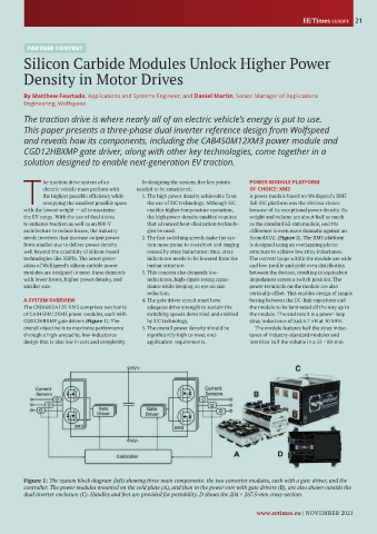
Figure 1: The system block diagram (left) showing three main components: the two converter modules, each with a gate driver, and the
controller. The power modules mounted on the cold plate (A), and then in the power core with gate drivers (B), are also shown outside the
dual inverter enclosure (C). Handles and feet are provided for portability. D shows the 204 × 267.5-mm cross-section.
www.eetimes.eu | NOVEMBER 2021