
Page 46 - EE Times Europe Magazine | February 2020
P. 46
44 EE|Times EUROPE — Boards & Solutions Insert
AUTOMOTIVE POWER
PCB Design Hints for Improving engines, including spark-ignition (SI) as well
IGBT Thermal Performance as the more efficient, compressed-ignition
(CI) types.
To address the demand for more efficient,
By Maurizio Di Paolo Emilio less polluting engines, vehicle manufacturers
are following three basic strategies:
• Engine right-sizing and hybridization.
limate change and society’s growing Thermal management and cooling solu- These techniques resize the engine based
sensitivity to environmental issues tions are a growing concern for IGBTs because on the class of the vehicle, maintain-
require the development of technical of increased heat loss in their application. ing the same power value. As a result, a
Csolutions for fossil-fuel–powered Heat losses fall into two categories: conduc- higher number of revolutions is obtained,
vehicles. Regulatory mandates for progressive tion losses and switching losses. which in turn involves a higher switching
reductions in emissions dictate the design Conduction losses occur during the frequency of the injection system and
of internal-combustion engines with lower switched-state voltage drop through the higher operating temperatures.
volumes, higher engine revs, and the ability to IGBT and depend on the current being con- • Dilution of the mixture. This approach
operate with less rich fuel mixtures. ducted. The loss of switching power occurs requires the use of wider gaps (necessary
during the switch-on and switch-off phases for proper heat dissipation) and higher
Insulated-gate bipolar of the IGBT and is dependent on the current, voltages for triggering the spark plug.
transistors used in ignition operating cycle, switching voltage, and Therefore, it is necessary to use IGBTs
switching frequency.
with higher operating voltages.
systems must withstand COMBUSTION ENGINE’S EVOLUTION • Direct injection during the compres-
sion stroke. This technique causes the
high currents and have high New emissions regulations require substantial formation of an area rich in combustible
clamping voltages under changes to the design of internal-combustion mixture near the spark plug, maintaining
operating conditions that will
inevitably produce a greater
amount of heat.
Those technological imperatives inevitably
have implications for the operating condi-
tions of insulated-gate bipolar transistors
(IGBTs) used in engine ignition and control
systems: The devices must attain higher
clamping voltages and switching frequencies, Figure 1: impli ed diagram o the test circuit (Image: Littelfuse)
with the attendant ability to dissipate
excess heat.
Here, we consider the effects on the ther-
mal performance of IGBTs using different
thermal PCB pads under different operating
conditions.
IGBTS AND THERMAL PERFORMANCE
The operating junction temperature (T vj(op) )
is fundamental to the operation of the
device and should be considered as a prac-
tical value. When calculating the junction
temperature for normal switching using con- Figure 2: PCB pads considered during the thermal analysis (Image: Littelfuse)
duction losses, switching losses, and thermal
impedance, the junction temperature must
always remain between the specified mini-
even in
mum and maximum values of T vj(op )
overload situations.
In practice, before the last switching event,
the temperature of the joint must remain
max. The transient temperature
below T vj(op )
increases that result from switching losses
in the switching event can be ignored,
provided that the device is used within its
safe operating area and that T vj does not
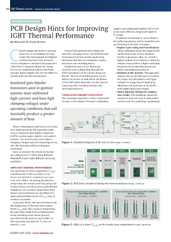
exceed T vj max. Figure 3: Effect of a lower V ce(ON ) on the steady-state temperature (Image: Littelfuse)
FEBRUARY 2020 | www.eetimes.eu