
Page 47 - EE Times Europe Magazine | February 2020
P. 47
EE|Times EUROPE — Boards & Solutions Insert 45
PCB Design Hints for Improving IGBT Thermal Performance
of pads made on the PCB (Figure 2) and kept
operative for a time that’s sufficient to reach a
stable temperature.
The test was conducted using a PCB with
five types of pads, each with its own thermal
conduction (Figure 2). More precisely, the
test used:
• a pad in which there is no heat conduc-
tion path from the collector of the IGBT
to the PCB (PAD 0);
• a pad with the same area as the IGBT
package (PAD 1)
• a pad with the same area as the IGBT
(PAD 2); and
• two pads with the recommended pad
area for the specific device, without
(PAD 3) and with thermal heat spreads
from the top to the bottom of the PCB
(PAD 4).
To quantify the improvement in thermal
performance attributable to a lower ce(ON) ,
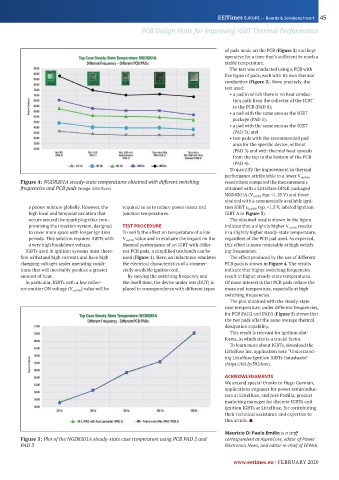
Figure 4: NGD8201A steady-state temperatures obtained with different switching researchers compared the measurements
frequencies and PCB pads (Image: Littelfuse) obtained with a Littelfuse DPAK-packaged
NGD 201A ( ce(ON) typ. 1. ) and those
obained with a commercially available igni-
a poorer mixture globally. owever, the required so as to reduce power losses and tion IGBT ( Vce(ON) typ. 1. , labeled Ignition
high local and temporal variation that junction temperatures. IGBT A in Figure 3).
occurs around the spark plug risks com- The obtained results shown in the figure
promising the injection system, designed TEST PROCEDURE indicate that a slightly higher ce(ON) results
to cover more space with longer ignition To verify the effect on temperature of a low in a slightly higher steady-state temperature,
periods. This solution requires IGBTs with V ce(ON) value and to evaluate the impact on the regardless of the PCB pad used. As expected,
a very high breakdown voltage. thermal performance of an IGBT with differ- this effect is more noticeable at high switch-
IGBTs used in ignition systems must there- ent PCB pads, a simplified testbench can be ing frequencies.
fore withstand high currents and have high used (Figure 1). Here, an inductance emulates The effect produced by the use of different
clamping voltages under operating condi- the electrical characteristics of a commer- PCB pads is shown in Figure 4. The results
tions that will inevitably produce a greater cially available ignition coil. indicate that higher switching frequencies
amount of heat. By varying the switching frequency and result in higher steady-state temperatures.
In particular, IGBTs with a low collec- the dwell time, the device under test (DUT) is Of more interest is that PCB pads reduce the
tor-emitter ON voltage ( ce(ON) ) value will be placed in correspondence with different types measured temperature, especially at high
switching frequencies.
The plot obtained with the steady-state
case temperature, under different frequencies,
for PCB PAD2 and PAD3 (Figure 5) shows that
the two pads offer the same average thermal
dissipation capability.
This result is relevant for ignition plat-
forms, in which size is a crucial factor.
To learn more about IGBTs, download the
Littelfuse Inc. application note “Understand-
ing Littelfuse Ignition IGBTs Datasheets”
(https://bit.ly/392deov).
ACKNOWLEDGMENTS
We extend special thanks to ugo Guzm n,
applications engineer for power semiconduc-
tors at Littelfuse, and os Padilla, product
marketing manager for discrete IGBTs and
ignition IGBTs at Littelfuse, for contributing
their technical assistance and expertise to
this article. ■
Maurizio Di Paolo Emilio is a staff
Figure 5: Plot of the NGD8201A steady-state case temperature using PCB PAD 2 and correspondent at AspenCore, editor of Power
PAD 3 Electronics News, and editor-in-chief of EEWeb.
www.eetimes.eu | FEBRUARY 2020