
Page 9 - PEN eBook July 2022
P. 9
Cover Story - Design Cover Story - Design
converters have a bulk
L1 DC-DC converter capacitor in parallel with
the input impedance on
+ Cbulk the input side, so it is
220 μF, 35 V common to take the ESR
as the input impedance.
RL ESR The ESR value is usually
VA C1 VE
50 Ω 100 mΩ in the range of 0.1 Ω to
1 Ω.
Vnoise
For example, if we
use the WCAP-AS5H
Figure 1: Input filter for a DC/DC converter, here a CL topology 865230557007 from
Würth Elektronik as the
bulk capacitor, then the
ESR value is 100 mΩ. If we now want to achieve a filter characteristic with an attenuation of
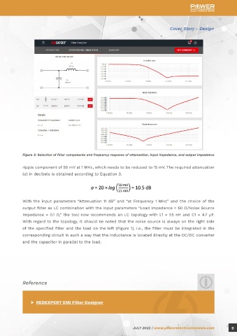
35 dB at 350 kHz, the tool recommends a CL circuit (Figure 2) and determines the values of the Figure 3: Selection of filter components and frequency response of attenuation, input impedance, and output impedance
components to be C1 = 47.0 µF and L1 = 240 nH. Figure 3 also shows the frequency response of
attenuation, input impedance, and output impedance. ripple component of 50 mV at 1 MHz, which needs to be reduced to 15 mV. The required attenuation
(a) in decibels is obtained according to Equation 3.
With the input parameters “Attenuation 11 dB” and “at Frequency 1 MHz” and the choice of the
output filter as LC combination with the input parameters “Load Impedance = 50 Ω/Noise Source
Impedance = 0.1 Ω,” the tool now recommends an LC topology with L1 = 55 nH and C1 = 4.7 µF.
With regard to the topology, it should be noted that the noise source is always on the right side
of the specified filter and the load on the left (Figure 1); i.e., the filter must be integrated in the
corresponding circuit in such a way that the inductance is located directly at the DC/DC converter
and the capacitor in parallel to the load.
Figure 2: Start page of the REDEXPERT EMI Filter Designer for entering filter parameters, followed by a suggestion for a
suitable filter topology
Reference
OUTPUT FILTER FOR DC/DC CONVERTERS
Due to the high switching frequencies commonly used in DC/DC converters today, an output filter ▶ REDEXPERT EMI Filter Designer
is required to reduce high-frequency noise and ripple. For example, the output voltage might have a
8 JULY 2022 | www.powerelectronicsnews.com JULY 2022 | www.powerelectronicsnews.com 9