
Page 6 - PEN eBook July 2022
P. 6
COVER STORY – DESIGN Cover Story - Design
other applications can be calculated. The goal of a filter circuit is to realize a defined insertion loss
in the selected frequency range. This is achieved with a high impedance over the desired frequency
range by the largest possible mismatch between load and source. Here, the insertion loss (a in
Equation 1) is defined as the ratio of the voltage without filter compared with the same circuit with
a filter. For a second-order LC filter, Equation 2 applies to the cutoff frequency (f ).
c
Equation 1 Equation 2
However, Equation 2 assumes ideal components. The inductance does not take into account the
winding resistance or the capacitance between the windings, and for the capacitor the equivalent
series resistance (ESR) and the equivalent series inductance (ESL), etc.
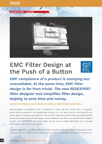
REDEXPERT EMI FILTER DESIGNER
EMC Filter Design at REDEXPERT EMI Filter Designer takes these parasitic elements into account in the frequency range
up to 30 MHz, so the simulation much more accurately reflects the real electrical behavior of the
the Push of a Button components and the filter characteristics up to fourth order.
The EMI Filter Designer determines the most suitable topology as a suggestion from the input
EMC compliance of a product is annoying but variable’s operating voltage, current, load/line impedance stabilization network and interference
source impedance, cutoff frequency, and attenuation at a defined frequency.
unavoidable. At the same time, EMC filter
design is far from trivial. The new REDEXPERT A total of six topologies are available for filters from second to fourth order: LC, CL, Pi (CLC),
T (LCL), LC-LC, and CL-CL.
filter designer tool simplifies filter design, After selecting the topology, the software calculates the discrete component values and simulates
helping to save time and money. the frequency responses of gain, input impedance, and output impedance of the filter. A summary
again shows the input values, the circuit, a BOM with an ordering function, and the simulated
By Gerhard Stelzer, senior technical editor at Würth Elektronik eiSos frequency responses. The calculation and the following automatic selection of the component
values is based on a Butterworth characteristic with the corresponding position of the poles.
Electromagnetic compatibility (EMC) compliance is often the last hurdle that an electronic
device has to overcome in the development process. It is not rare at all for circuit-specific and PRACTICAL EXAMPLE WITH REDEXPERT EMI FILTER DESIGNER
layout-specific changes to be required in the process. These then extend the product development REDEXPERT EMI Filter Designer is an online tool at www.we-online.com/filter-designer that is
cycle and increase costs. For this reason, Würth Elektronik now offers the new EMI Filter Designer suitable for designing an input or output filter for AC/DC or DC/DC converters, etc. A typical input
as part of its REDEXPERT tool family, which can be used to design EMC filters for conducted filter for a DC/DC converter is shown in Figure 1. The main goal of the filter tool is to calculate a
differential-mode interference signals. clean signal attenuation for defined input parameters by achieving maximum impedance mismatch.
A typical application is an input filter for DC/DC converters, especially switching regulators, which ASYMMETRICAL INPUT FILTER FOR DC/DC CONVERTERS
can generate a lot of interference. In the same way, filters for attenuating broadband interference in A good filter design requires the most accurate input specifications possible. In reality, DC/DC
6 JULY 2022 | www.powerelectronicsnews.com JULY 2022 | www.powerelectronicsnews.com 7