
Page 8 - PEN Ebook March 2021
P. 8
Cover Story - Design Cover Story - Design
in one transmitter to enable more comfortable load requirements (e.g. battery). The receiver phones with wireless charging capabilities. To be able to detect much smaller objects at higher
positioning of the receiver devices. A MOSFET usually also contains a wireless power control- ensure safe wireless power operations as well as power levels.
and driver architecture is then used to switch on ler for communication and system management. interoperability between transmitters and receiv-
the coil with the best coupling to the receiver to Infineon offers a full range of semiconductors for ers across OEMs, a standards body supported by Thermals
optimize system efficiency. wireless power systems, from MOSFETs and driv- major consumer electronics and semiconductor In order for the system to operate safely, certain
ers, over MCUs and HW authentication, to BT/BLE corporations is defining the standard for induc- temperature limitations need to be met on the
The transmitter's magnetic field induces an AC and USB-PD controllers. For more information tive wireless charging: the Wireless Power Con- transmitter and the receiver side. In the WPC Qi
voltage waveform on the receiver side, which is browse the application brochure. sortium (WPC). Infineon and Spark Connected are standard, certain temperature thresholds have to
rectified into DC voltage using a diode or bridge both parts of the WPC and actively contribute to be met during operation. At lower power levels,
rectifier. A regulation stage on the receiver side The Qi standard, which is the dominating stand- the next-generation wireless power technologies, a slightly lower efficiency is not so critical be-
conditions the voltage such that it meets the ard for wireless charging, is applied in smart- especially in the higher power area. cause the losses do not heat up the surroundings
significantly. However, at higher power levels,
previously small losses will result in large heat
CHALLENGES IN HIGHER POWER dissipation and a stop of operation. Thus, higher
WIRELESS CHARGING power wireless charging requires much higher
In higher power designs, several design challeng- efficiency figures.
es are amplified compared to lower power wire-
less charging due to the higher power levels.
THE MINOTAUR – A
Communication GROUNDBREAKING 45 W
In the WPC Qi standard, the communication be- TRANSMITTER AND RECEIVER
tween the transmitter and the receiver is enabled SOLUTION
via in-band communication. However, when mov- Spark Connected and Infineon solve these chal-
ing into higher power levels, harmonic distortions lenges in their 45 W wireless charging solution
of the AC signal can lead to package loss and an called "The Minotaur". By carefully selecting the
increasingly difficult communication between the components and architecting the solution, the
transmitter and the receiver. This needs to be Minotaur can wirelessly transmit up to 45 W of
addressed to enable a reliable high-power wire- power with high efficiency. It is fully interoper-
less charging operation. able with the current WPC Qi standard, meeting
communication, thermal, and FOD requirements.
FOD Thus, a Minotaur receiver can be charged on a
FOD is a crucial feature to enable safe wireless WPC Qi transmitter, and a WPC Qi receiver can
power operation. The WPC Qi standard defines charge on the Minotaur transmitter.
certain power thresholds that have to be sur-
passed for foreign object detection to be acti- Out-of-band communication via
vated accurately, not to have the wireless power Bluetooth
transfer being stopped unnecessarily. However, in Communication in the WPC Qi standard works via
higher power levels, the same small foreign ob- in-band communication at a frequency of 80-
ject, which might not have heated up significantly 200 kHz. Communication from the transmitter to
at low power (e.g. 5 W), will heat up much more the receiver side is achieved by frequency shift
(at, e.g. 45 W) and hence pose a safety hazard. keying (FSK) through the wireless power con-
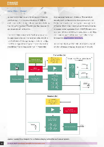
Figure 2: General block diagram for a wireless charging transmitter and receiver system. Thus, FOD needs to be much more accurate and troller, slightly adapting the MOSFETs' switching
8 MARCH 2021 | www.powerelectronicsnews.com MARCH 2021 | www.powerelectronicsnews.com 9