
Page 10 - PEN eBook October2023
P. 10
Cover Story — Design
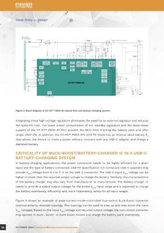
Figure 3: Block diagram of EZ-PD™ PMG1-B1–based five-cell battery-charging system
Integrating these high-voltage regulators eliminates the need for an external regulator and reduces
the system’s cost. The lower power consumption of the standby regulators and the deep-sleep
support of the EZ-PD™ PMG1-B1 MCU prevent the MCU from draining the battery pack and offer
longer shelf life. In addition, the EZ-PD™ PMG1-B1’s USB PD block has an internal dead battery R
d
that allows the device to make a power delivery contract with any USB-C adapter and charge a
depleted battery.
CRITICALITY OF BUCK-BOOST/BATTERY-CHARGER IC IN A USB-C
BATTERY-CHARGING SYSTEM
In battery-charging applications, the power conversion needs to be highly efficient for a given
input and the type of battery connected. USB PD Specification 3.0–compliant USB-C adapters may
provide V voltage from 5 V to 21 V on the USB-C connector. The USB-C input V voltage can be
BUS BUS
higher or lower than the required output voltage to charge the battery. Similarly, the characteristics
of the battery charger may also vary from manufacturer to manufacturer. The battery-charger IC
needs to provide a stable output voltage for the entire V input range and is expected to charge
BUS
the battery seamlessly, efficiently and, more importantly, safely for all input ranges.
Figure 4 shows an example of peak-current-mode–controlled four-switch buck-boost converter
(without polarity reversal) topology. This topology can be used to step up and step down the input
V voltages. Based on the input V voltage and required output voltage, the buck-boost converter
BUS BUS
may operate in buck-, boost- or buck-boost modes and charge the battery pack seamlessly.
10 OCTOBER 2023 | www.powerelectronicsnews.com