Page 14 - PEN eBook July 2023
P. 14

Cover Story — Design


                                                                           ▶  Enable feature: This sets the
                                                                           converter  to  start  switching
                                                                           when the threshold is reached.

                                                                           ▶  Power     Good     feature:
                                                                           Once  V     is  above  a  certain
                                                                                  OUT
                                                                           threshold—e.g.,  90%—the  PG
                                                                           pin transitions to a high state.


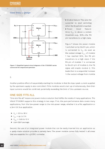
                                                                           Figure 7 shows the power module
                                                                           1 switched on by the EN pin, which
                                                                           is  connected  to  V .  As  soon  as
                                                                                              IN
                                                                           the output voltage V    of module
                                                                                               OUT1
                                                                           1  has  reached  90%,  the  PG  pin
                                                                           transitions to  a high  state.  If the
                                                                           PG  pin  of  module 1  is  connected
            Figure 7: Simplified typical circuit diagram of the 1710X3801 series   to the EN pin of module 2, the PG
            connected for sequenced operation                              signal  will  enable  module  2.  This
                                                                           leads then to a sequential increase
                                                                           in the output voltage from module

            2.


            Another positive effect of sequentially starting the modules is that the input peak current supplied
            by the upstream supply is also controlled. If the modules would start up simultaneously, then their
            input currents would be combined, potentially exceeding the limit of the upstream source.


            ONE SIZE FITS ALL
            “One size fits all” means one power module solution that fulfills the needs of many applications. The
            VDLM 1710X3801 supports this strategy in two ways. First, the pure performance data covers many

            applications, from the low-power range to the mid-power range, whether it is a PoL application or
            a 24-V DC bus application.


             ▶   V  = 3.5 to 38 V
                  IN
             ▶   I   = up to 3 A
                 OUT
             ▶   V   = 0.85 to 13 V
                  OUT
             ▶   LGA-12EP package


            Second, the use of an integrated power module that can be easily inserted into an application as
            a ready-made solution provides a remedy here. The power module comes fully tested in all areas
            that are essential for a DC/DC converter.


  14        JULY 2023 | www.powerelectronicsnews.com
   9   10   11   12   13   14   15   16   17   18   19