
Page 9 - PEN eBook July 2023
P. 9
Cover Story — Design
Two load states are very common:
▶ Light load, in which the application operates in idle or standby mode (reduced energy
consumption)
▶ Full load, in which the application operates under nominal conditions (normal energy
consumption)
What would be the best switching behavior for each load condition? If the two characteristics
mentioned are related to a DC/DC power module, that means little or no switching takes place at
light loads and switching is responsible for most of the losses. In order to realize this, adaptive
switching behavior is needed, i.e., two modes with different switching behavior and a system
intelligent enough to transition between modes based on the load demands.
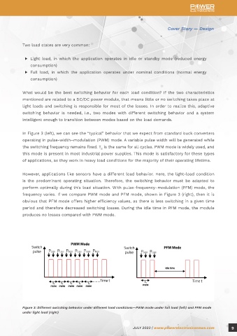
In Figure 3 (left), we can see the “typical” behavior that we expect from standard buck converters
operating in pulse-width–modulation (PWM) mode. A variable pulse width will be generated while
the switching frequency remains fixed. T is the same for all cycles. PWM mode is widely used, and
S
this mode is present in most industrial power supplies. This mode is satisfactory for these types
of applications, as they work in heavy load conditions for the majority of their operating lifetime.
However, applications like sensors have a different load behavior. Here, the light-load condition
is the predominant operating situation. Therefore, the switching behavior must be adapted to
perform optimally during this load situation. With pulse-frequency–modulation (PFM) mode, the
frequency varies. If we compare PWM mode and PFM mode, shown in Figure 3 (right), then it is
obvious that PFM mode offers higher efficiency values, as there is less switching in a given time
period and therefore decreased switching losses. During the idle time in PFM mode, the module
produces no losses compared with PWM mode.
Figure 3: Different switching behavior under different load conditions—PWM mode under full load (left) and PFM mode
under light load (right)
JULY 2023 | www.powerelectronicsnews.com 9