
Page 7 - PEN_Ebook_October2021
P. 7
DESIGN Design
The switching performance of SiC MOSFETs
is controlled by the gate drive. The voltage
source gate drive (VSG) is the most widely used
structure of the MOSFETs, as it is low-cost
and has a simplified structure .9–13 As the gate
current decreases, a rise can be seen in the
gate voltage. This rise becomes constant when
the Miller plateau phenomenon occurs; this
happens when the gate drive output voltage Figure 1: Gate current during the turn-on transient
is at a constant rate. This whole process has
1
been shown in Figure 1. To increase the power device’s switching speed, the gate current needs to
be enhanced as the switching transient occurs 14–17 , and for this purpose, the current source gate
has been designed. The original article can be found here.
CHARGE PUMP GATE DRIVE (CPG)
A limited amount of gate current is the reason for an increased turn-on switching speed of SiC
MOSFETs. To find a solution, further research concerning the factors affecting the gate current
in between the process of turn-on transient with a typical VSG is needed. The rating of the gate
voltage of the SiC MOSFETs is 20 V. Two main requirements in the switching procedure are available
1
Charge Pump for the gate drive: First, a sufficient amount of gate current should be provided by the gate drive to
reduce the switching time during the switching transient phase. Second, the gate drive should be
Gate Drive for the able to keep the gate voltage under control during the transient and steady state.
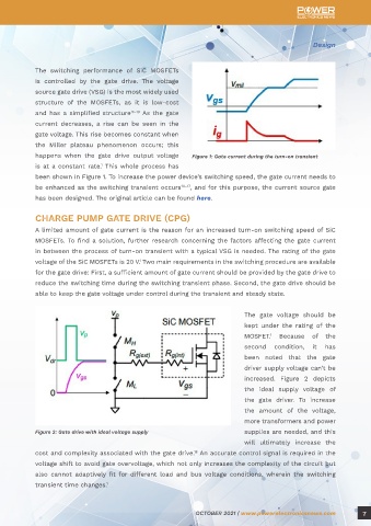
Improvement of the The gate voltage should be
kept under the rating of the
MOSFET. Because of the
1
Turn-On Transient of SiC second condition, it has
been noted that the gate
MOSFETs driver supply voltage can’t be
increased. Figure 2 depicts
the ideal supply voltage of
By Maurizio Di Paolo Emilio, editor-in-chief of Power Electronics News and the gate driver. To increase
EEWeb the amount of the voltage,
more transformers and power
One of the most promising devices for high-power and high-frequency applications is the SiC Figure 2: Gate drive with ideal voltage supply supplies are needed, and this
MOSFET. 2–3 It supports higher junction temperature, and its features include low on-resistance will ultimately increase the
and higher switching. SiC MOSFETs allow building converters with higher power density and higher cost and complexity associated with the gate drive. An accurate control signal is required in the
18
efficiency. The widespread adoption of SiC MOSFETs is, however, limited by their switching loss. voltage shift to avoid gate overvoltage, which not only increases the complexity of the circuit but
Most of the loss occurs in the turn-on phase, as presented in the datasheets of the device and in also cannot adaptively fit for different load and bus voltage conditions, wherein the switching
the results of the reported testing. 4–8 transient time changes. 1
6 OCTOBER 2021 | www.powerelectronicsnews.com OCTOBER 2021 | www.powerelectronicsnews.com 7