
Page 20 - PEN_Ebook_October2021
P. 20
INDUSTRIAL Industrial
Many electronic devices will use a DC/DC buck converter to down-convert to the required supply
voltage, regulating the output voltage based on a reference voltage. An oscilloscope is a standard
tool for circuit development and debugging; if the oscilloscope is restricted to time-domain
measurements only, one way to attempt to measure the stability of the converter is to test the
load-step response against time. The setup is problematic: For an accurate test, the rise and fall
times for the steps need to be extremely fast and the load generator must correspondingly switch
quickly. Even if the performance of the load generator itself is adequate for the task, the input
from the load generator needs to be extremely close to the output from the converter to prevent
parasitic effects developing in the rail; in many cases, the restrictions of the circuit layout will make
it physically impossible to input the load close enough. In principle, the buck converter requires
a precise reference voltage to maintain a constant output voltage as the current rises and falls
with the changes in load (see Figure 1). While a regulation loop provides feedback from the output
current to the reference source, the degree of regulation has its limits.
Shining a Light on LED
Driver Stability
By Marcus Sonst, application development engineer at Rohde & Schwarz
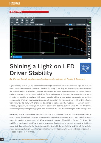
Figure 1: Current (left) and voltage (right) for the load-step response of a DC rail with a nominal 1.2-V potential
difference. Despite the feedback loop, the voltage drops and peaks as the load increases and decreases; these changes
Light-emitting diodes (LEDs) have many advantages compared with incandescent light sources, so in voltage are unavoidable.
it was inevitable that in all conditions suitable for using LEDs, they would quickly begin to dominate
the technology for illumination. The main advantages are lower power consumption, longer lifetime, In fact, there is an even more fundamental issue, apart from difficulties of measuring the load-step
and more robust, smaller, faster switching. The disadvantage is the need for supporting electronic response. The aim of the measurement is to investigate the converter stability; the results of the
circuits to provide a regulated DC power supply, which brings added complexity as well as load-step test do not provide any information about the available margin. However, it is the size of
components. While an incandescent source will generate light from anything — AC or DC, voltages the margin that must be known to evaluate stability.
from very low to high, with enormous tolerance to spikes and fluctuations — an LED requires
a stable, regulated, low-voltage DC current source and optimal current level. An LED driver is a Fortunately, an alternative stability test method exists and will be performed in the frequency
current regulator, aiming to supply the ideal current to the LED despite changes in the voltage level. domain. For meaningful closed-loop measurements, an oscilloscope with frequency-domain
capabilities is required. For a closed-loop measurement to be possible, an error signal (error
Depending on the available electricity source, an AC/DC converter or DC/DC converter is required — voltage) must be added to the loop to represent the input voltage. As long as the added injection
usually some form of switch-mode power supply. A switch-mode power supply, as a high-frequency resistance is small, compared with the input impedance of the feedback loop, its influence on the
switching device, is by nature a significant potential source of instability. For an LED driver, the voltage will be negligible.
stability is particularly significant, as any unwanted fluctuations in current are rapidly visible as
unwanted fluctuations in the light generated by the LED. So testing the stability of the switch- The injection point must be carefully selected, as it should not influence the DC operating point. A
mode power supply is an essential task in LED driver development. Consequently, it is important to low-impedance path is required at the output probe and a high-impedance path at the input probe.
select a suitable test method. The frequency-response analyzer of the oscilloscope measures the two voltages and calculates
50 OCTOBER 2021 | www.powerelectronicsnews.com OCTOBER 2021 | www.powerelectronicsnews.com 51