Page 28 - PEN Ebook March 2021
P. 28

Design                                                                                                                                                                                                               Design


          Table 1: Summary of Effect of Switching Frequency Increasing on BW/PM.
          the requirement set by Equation (10). Once again,    MPQ4430 BODE PLOT AT
          since the switching frequency is configurable in     DIFFERENT SWITCHING
          this part, the maximum configurable switching        FREQUENCIES

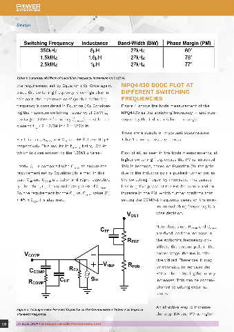
          frequency is considered in Equation (10). Consider-  Figure 4 shows the bode measurement of the
          ing the maximum switching frequency of 2.5MHz,       MPQ4430 as the switching frequency — and con-
          the target COMP-P frequency (f COMP-P ), must be set   sequently the inductor value — change.
          close to f  / 2 = 2.5MHz / 2 = 1.25MHz.
                  SW
                                                               There are a couple of important observations;
          For this part, R COMP  and C  are 460kΩ and 0.2pF,   Table 1 summarizes the results.
                                  HF
          respectively. This results in f COMP-P  being 1.7MHz,

          which is close enough to the 1.25MHz target.         First of all, as seen in the bode measurements, at                Figure 6: Bode Diagram of MPQ4430 at 2.5MHz With and Without Feed-Forward Capacitor.
                                                               higher switching frequencies the PM is improved.
          Lastly, C  is compared with C COMP  to ensure the    This is because, based on Equation (2), the pole                  switching frequencies is by adding a feed-for-       CONCLUSION
                  HF
          requirement set by Equation (11) is met. In this     due to the inductor (ω ) is pushed further out as                 ward capacitor (C ) to the feedback network (see     This article presented a systematic approach
                                                                                     L
                                                                                                                                                  FF
          part, C  and C COMP  are 0.2pF and 52pF, respective-  the switching frequency increases. This causes                   Figure 5).                                           to evaluate the capability of the internal com-
                HF
          ly. Therefore, C  is approximately 0.3% of C COMP .   less negative phase at the BW frequency and an                                                                        pensation networks based on the application
                        HF
          So, the requirement for the C  vs. C COMP  value (C    increase in the PM, which further confirms that                 Adding a feed-forward capacitor can great-           switching frequency. The proposed evaluation
                                                        HF
                                      HF
          < 4% x C COMP ) is also met.                         setting the COMP-Z frequency based on the min-                    ly improve the BW and PM of the system. The          technique involved three basic checks to ensure
                                                                                imum switching frequency is a                    frequency response of the MPQ4430 was taken          that the internal compensation network is prop-
                                                                                wise decision.                                   at a 2.5MHz switching frequency, both with and       erly designed for an application with a known
                                                                                                                                 without a 20pF feed-forward capacitor. With the      or configurable switching frequency. In certain
                                                                                Note that, since R COMP  and C COMP              additional capacitor, BW and PM improved.            cases, adding external knobs can further improve
                                                                                are fixed, and the increase in                                                                        the transient performance of the system. These
                                                                                the switching frequency only                                                                          principles were applied to the MPQ4430, which
                                                                                affects the second pole in the                                                                        verified the effectiveness of the technique.
                                                                                power stage, the BW is rela-

                                                                                tively fixed. Therefore, it may
                                                                                be desirable to increase the
                                                                                BW as the switching frequency                    For More Information
                                                                                increases. This can be accom-
                                                                                plished by adding external                              ▶ Monolithic Power Systems
                                                                                knobs.


                                                                                                                                        ▶ Buck Regulators
                                                                                An effective way to increase
          Figure 5: Adding a Feed-Forward Capacitor to the Compensation Network to Improve
          Transient Response.                                                   the loop BW and PM at higher

  28      MARCH 2021 | www.powerelectronicsnews.com                                                                                                                                         MARCH 2021 | www.powerelectronicsnews.com       29
   23   24   25   26   27   28   29   30   31   32   33