Page 26 - PEN Ebook March 2021
P. 26

Design                                                                                                                                                                                                               Design


                                                                                                                                 increases as the inductance (L) is reduced. As ω     CASE STUDY – THE MPQ4430
                                                                                                                                                                                L
                                                                                                                                 increases, the phase delay caused by this pole is    Let’s explore these principles in a real part. The
                                                                                                                                 also pushed further out from the BW frequency.       MPQ4330 from MPS is a 36V, 3.5A, synchro-
                                                                                                                                 The reduction in the negative phase induced by       nous step-down converter with integrated FETs
                                                                                                                                 this pole results in an increase in the system’s     and integrated compensation network. Figure 3
                                                                                                                                 overall phase, and consequently the system’s PM.     shows the typical application schematic of the
                                                                                                                                                                                      MPQ4430 and the internal compensation net-
                                                                                                                                 Therefore, if COMP-Z is set based on the mini-       work. The switching frequency is set using a
                                                                                                                                 mum configurable switching frequency, the Phase      resistor at the FREQ pin. Based on the resistor
                                                                                                                                 Margin (PM) will increase as the switching fre-      value, the switching frequency of this part can

                                                                                                                                 quency increases.                                    range between 350kHz and 2.5MHz.
          Figure 3: The MPQ4430 Typical Application and Internal Compensation Network.
                                                                                                                                 Unlike COMP-Z, the COMP-P frequency is set           Since the switching frequency is configurable in this
          PARTS WITH CONFIGURABLE                               ▶    COMP-P is set based on the maximum con-                     based on the maximum configurable switching          part, the approach discussed in the previous section
          SWITCHING FREQUENCY                                      figurable switching frequency.                                frequency. As discussed earlier, the magnitude/      must be followed. COMP-Z must be set based on

          Similar approaches can be applied to parts with                                                                        angle due to a pole starts descending at 10% of      the minimum switching frequency, which is 350kHz.
          configurable switching frequencies, as long as       COMP-Z is set based on the minimum configur-                      the frequency of that pole. Let’s assume that

          two critical points are considered:                  able switching frequency because as the switch-                   f COMP-P  was set based on the minimum switch-       Assuming a 350kHz switching frequency, the
                                                               ing frequency increases, the inductor size is re-                 ing frequency. Now, if the part was configured to    target BW would be 10% of that, which is 35kHz.
           ▶    COMP-Z is set based on the minimum con-        duced proportionally. When looking at the second                  operate at the maximum switching frequency,          Now, let’s calculate the COMP-Z frequency based
             figurable switching frequency.                    pole in a PCM buck regulator power stage (repre-                  the phase reduction due to f COMP-P  (which starts   on the compensation network passive compo-
                                                               sented by Equation (2)), the pole frequency (ω )                  taking effect from 0.1 x f COMP-P ) would occur inside   nents. In this part, R COMP  and C COMP  are 460kΩ and
                                                                                                            L
                                                                                                                                 its BW. This is not recommended, as it places an-    52pF, respectively. Using Equation (6), this results
                                                                                                                                 other pole inside the BW. Since there is only one    in f COMP-Z  being 6.6kHz. This value is within the ac-
                                                                                                                                 zero available in a Type II compensation network,    ceptable range of 4kHz to 8kHz based on Equa-
                                                                                                                                 it cannot compensate for this pole. Therefore,       tion (9), which means the first requirement is met.

                                                                                                                                 the COMP-P frequency must be set based on the
                                                                                                                                 maximum switching frequency of the part.             Next, the COMP-P frequency is checked against


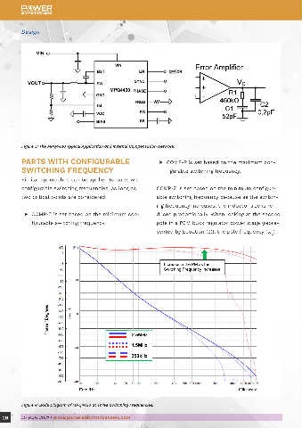
          Figure 4: Bode Diagram of MPQ4430 at Three Switching Frequencies.

  26      MARCH 2021 | www.powerelectronicsnews.com                                                                                                                                         MARCH 2021 | www.powerelectronicsnews.com       27
   21   22   23   24   25   26   27   28   29   30   31