
Page 8 - PEN_Ebook_December_2021
P. 8
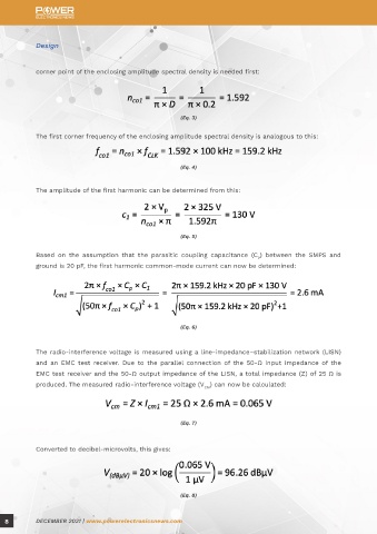
Design Design
corner point of the enclosing amplitude spectral density is needed first: The result of the calculation is
that high interference emissions
can be expected. For example, the
product family standard EN 55022
can be used here for assessment
(Eq. 3)
of the interference emission. In
The first corner frequency of the enclosing amplitude spectral density is analogous to this: the frequency range of 0.15 MHz to
0.5 MHz, it defines a permissible
quasi-peak weighted interference
(Eq. 4) level of 66 dBµV to 56 dBµV. Figure 2
shows the result of the measurement
The amplitude of the first harmonic can be determined from this: of the conducted radio-interference
voltage of this SMPS without line
filter.
Figure 2: Radio-interference voltage of an SMPS without line filter
The measurement shows that a line filter is absolutely essential.
(Eq. 5)
Based on the assumption that the parasitic coupling capacitance (C ) between the SMPS and DESIGN OF A LINE FILTER
P
ground is 20 pF, the first harmonic common-mode current can now be determined: Figure 3 shows the schematic design
of a simple single-phase line filter.
Würth Elektronik provides various
models of line chokes, such as the
WE-CMB series, for the construction
of line filters. A line choke basically
(Eq. 6)
consists of a manganese-zinc ring core,
on which there are two geometrically
The radio-interference voltage is measured using a line-impedance–stabilization network (LISN) separated windings wound in opposite
Figure 3: Single-phase line filter
and an EMC test receiver. Due to the parallel connection of the 50-Ω input impedance of the directions. Figure 4 shows the design
EMC test receiver and the 50-Ω output impedance of the LISN, a total impedance (Z) of 25 Ω is of the WE-CMB. In this case, the
produced. The measured radio-interference voltage (V ) can now be calculated: WE-CMB acts like a filter coil, which
CM
counteracts the current and reduces
its amplitude. A common-mode
choke with an as-low-as-possible
(Eq. 7)
self-resonance frequency (SRF) in
the lowest-frequency range should
Converted to decibel-microvolts, this gives: be selected because the SMPS used
here switches with very low pulse
frequency. Low SRF causes high
attenuation in the lower-frequency
range. Figure 4: Design of the WE-CMB
(Eq. 8)
8 DECEMBER 2021 | www.powerelectronicsnews.com DECEMBER 2021 | www.powerelectronicsnews.com 9