
Page 11 - PEN_Ebook_December_2021
P. 11
Design Design
Figure 5 shows the characteristic capacitors. The oscillation equation is now converted and used to determine the Y capacitance:
curve of the attenuation for the
WE-CMB, size XS with 39-mH
inductance, in the 50-Ω system.
A distinction is always made in the (Eq. 10)
attenuation between the common-
mode (black line) and differential- As two Y capacitors are needed,
mode (red, dashed line) suppression. the calculated value is divided by
In common-mode operation, the 2. Y capacitors conduct common-
WE-CMB line choke reaches its mode interference from the SMPS
maximum attenuation at 150 kHz. back to PE. Depending on the
However, the attenuation drops device type, only leakage currents of
with increasing frequency. Other 0.25 mA to ≤3.5 mA are permissible;
X/Y capacitors are required because no capacitance with a value greater
the line filter should suppress than 4.7 nF should be used. Two Y
Figure 5: Attenuation of the WE-CMB XS 39 mH interference up to 30 MHz. An X capacitors with an E12 value of 2.2 nF
capacitor is placed both before as have been selected for this reason.
well as after the line filter to block differential-mode interference from the mains side and the Figure 6 shows the result of the
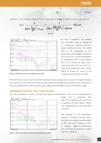
SMPS. With its leakage inductance, the WE-CMB in combination with the X capacitor forms a Figure 6: Radio-interference voltage with line filter measurement with this line filter.
low-pass filter, which reduces the differential-mode interference and subsequent common-mode
interference. Two X capacitors with a value of 330 nF have been selected here as an example. Their With the filter in circuit, the result of the radio-interference voltage test is a pass. The margin between
SRF is approximately 2 MHz. the respective interference limits and the quasi peak and average measurements at the frequency of
150 kHz is greater than 10 dB, and this margin significantly increases across the frequency range.
For safety reasons, a resistor must be placed on the mains side in parallel with the X capacitor
to discharge the capacitor if the SMPS is disconnected from the mains. A varistor should also be OPTIMIZATION OF THE LINE FILTER
placed before the line filter so that transient overvoltages from the mains are short-circuited. Würth It is also possible to further increase the signal-to-interference ratio in the lower-frequency
Elektronik disk varistors from the WE-VD series are ideally suitable for this. Overload protection range. Two X capacitors with
such as a fuse must also be considered, and this should always be placed before the varistor. The 330 nF are replaced with two 1.5-µF
protection trips in the case of a short-circuit by the varistor. Y capacitors are required for further X capacitors for this. Figure 7 shows
suppression of the common-mode interference. In combination with the WE-CMB, they form a the measurement of the optimized
corner frequency (f ), which is defined by the Thomson oscillation equation: line filter.
0
The change of the capacitance
causes a reduction of the radio-
interference voltage of approximately
(Eq. 9)
15 dB in the lower-frequency range.
Attenuation of 40 dB is required to achieve levels below the permissible interference level of A greater signal-to-interference
66 dBµV (at 150 kHz). This corresponds to two decades in the logarithmic representation. One-tenth ratio has been achieved and a good
of the pulse frequency is used as a factor for the corner frequency or further calculation of the Y line filter designed.
Figure 7: Radio-interference voltage with optimized line filter
10 DECEMBER 2021 | www.powerelectronicsnews.com DECEMBER 2021 | www.powerelectronicsnews.com 11