
Page 9 - Power Electronics News - December 2020
P. 9
Semiconductors Semiconductors
ing established Si MOSFETs and IGBTs. This is
achieved with parts in standard discrete pack-
ages making them easy to engineer into new and
existing designs.
The excellent efficiency gains realized with Gen
3 SiC FETs from UnitedSiC promoted widespread
adoption of the technology and now Gen 4 is
delivering an entirely new level of performance,
enabled by advancing fabrication and packaging
technology. With parts rated at 750V, designers
now have additional headroom over traditional
650V rated Si and SiC MOSFETs typically used in
Figure 1: UnitedSiC 750V Gen 4 SiC FET on-resistance per Figure 2: UnitedSiC 750V Gen 4 SiC FET R DS(ON) , EOSS FOM Figure 3: UnitedSiC 750V Gen 4 SiC FET R DS(ON) , C OSS(tr) FOM bus applications at low and medium power lev-
unit area compared to 650V rated SiC MOSFET competitors. compared to 650V rated SiC MOSFET competitors. compared to 650V rated SiC MOSFET competitors. els. With figures of merit that excel in all areas
ful comparison. The same UnitedSiC 18 milliohm WBG device switching is to operate at higher the gate drive arrangement, for an instant boost and convenient, thermally enhanced packages,
device as in Figure 1 is compared in Figure 2 with frequencies to reduce size, cost and weight of in performance. As a bonus, total gate charge of Gen 4 is set to enable new standards of efficien-
SiC MOSFET alternatives and the Gen 4 SiC FET associated components, particularly magnetics, SiC FETs is a few tens of nanocoulombs, so that cy and power density from chargers, rectifiers,
advantages are clear, 50% better FOM at 25°C and the extra low C OSS(TR) of Gen 4 SiC FETs is a dis- even when switched at high frequency, gate drive PFC stages and DC-DC conversion in all power
40% at 125°C. In hard-switching applications such tinct advantage. power required is minimal. Also, as in previous conversion and storage applications.
as the ‘Totem-Pole PFC’ or in standard 2-level generations, Gen 4 SiC FETs have robust ava-
inverters, stored charge in the body diode is also Gen 4 SiC FETs from UnitedSiC retain the ma- lanche and short circuit ratings.
important and is very low in SiC FETs, with just a jor advantage that they can be safely driven
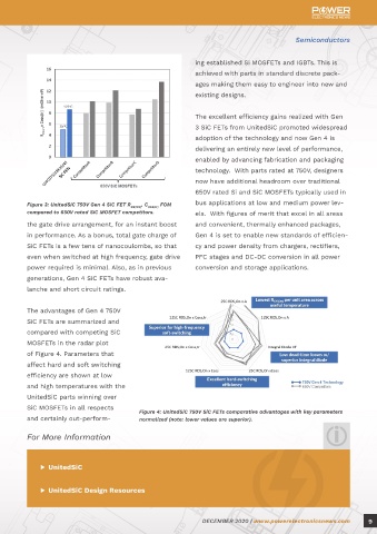
small contribution from the integral low voltage Si from fully off to saturation using a 0V-12V gate The advantages of Gen 4 750V
MOSFET. Although there is no parasitic body diode drive with a maximum of +/20V, clamped by SiC FETs are summarized and
as such in the integrated JFET, there is a reverse ESD protection diodes. The threshold voltage of compared with competing SiC
conduction path through the JFET channel and 5V allows unipolar operation. The device short MOSFETs in the radar plot
the body diode of the co-packaged Si MOSFET. circuit current is controlled by the JFET channel, of Figure 4. Parameters that
The body diode drop appears as the sum of a 0.7V which has a largely temperature-independent affect hard and soft switching
knee voltage from the Silicon MOSFET, and the threshold. Therefore, the short-circuit capabil- efficiency are shown at low
ohmic drop of the JFET channel, amounting to ity becomes independent of gate drive voltage and high temperatures with the
1.3V or less. This compares with a typical 650V SiC above 12V, a behavior quite unlike SiC MOSFET UnitedSiC parts winning over
MOSFET body diode which can drop more than 3V and IGBTs. The Miller effect is effectively absent, SiC MOSFETs in all respects
Figure 4: UnitedSiC 750V SiC FETs comparative advantages with key parameters
with hundreds of nanocoulombs of stored charge. avoiding the possibility of spurious turn-on and and certainly out-perform- normalized (note: lower values are superior).
packages offered include Kelvin connections to
As shown in Figure 3, soft-switching applications avoid source inductance being included in the For More Information
such as in LLC and PSFB converters also benefit gate drive loop which might otherwise couple
from using SiC FETs – while output capacitance transients into the gate drive. As with earlier SiC ▶ UnitedSiC
C OSS(TR ) is not discharged rapidly in these circuits, FET generations, the high maximum gate drive
it does introduce a delay at the switch turn-off voltage allows parts to be retrofitted into exist-
edge as it charges, which can limit maximum ing circuits to change out IGBTs, Si-MOSFETs and ▶ UnitedSiC Design Resources
useable frequency. As one of the attractions of SiC-MOSFETs with little or no modification to
8 DECEMBER 2020 | www.powerelectronicsnews.com DECEMBER 2020 | www.powerelectronicsnews.com 9