
Page 32 - EETEurope FlipBook February
P. 32
32 EE|Times EUROPE — Power Electronics
POWER ELECTRONICS
Miniature Current
Transformers Keep Pace
with GaN
BY GEORGE SLAMA, Senior Application Engineer, Würth Elektronik
s we begin to realize all the promises made to
us by the proponents of gallium nitride and
silicon carbide devices — the promises of faster,
Asmaller, and cheaper (someday) power conver-
sion devices — it’s important to note similar advances in
the related passive components. For a long time, higher
operating frequency meant smaller magnetics and capaci-
tors simply because the amount of energy storage required
per cycle decreased. For the same amount of total power,
the more units of energy per second, the smaller the unit
needed to be.
Current transformers are used for allows for high-side sensing; their power dis- turns ratios. Though the common turns ratios
control, protection, detection, or measure- sipation is very low compared with resistors, are the same as for larger current transform-
ment in power supplies. Current mode control especially at large currents; they have a high ers, the small size significantly lowers winding
requires measuring the peak currents and output signal, which provides better noise self-capacitance, extending the operating fre-
responding accordingly. Protection is usually immunity; the circuitry is simple, with no quency range well into the megahertz region,
related to overcurrent limits; detection is need for an operational amplifier; the single as shown in Figure 2.
knowing that a load or power supply is using primary can be integrated into the package;
current; and, finally, measurement is used they are rugged and compact; and they are Current transformers provide
when power consumption is needed. SMT-ready.
Current transformers have many advan- Current transformers are now available in galvanic isolation, low power
tages over other sensing methods. They a compact size based on EE5 and EE4.4 cores dissipation compared with
provide galvanic isolation, which easily like the WE-CST series, with many standard
resistors, a high output signal,
simple circuitry, and a rugged,
RP LLKG RS
compact, SMT-ready design.
IP The downside is lower magnetizing induc-
tance, which affects the low-end operating
LM RC CS RB
frequency and must be considered when
choosing a part for an application. As seen in
Figure 3, magnetizing current (I ) and core
m
1:n loss (I ) combine to form the exciting current
c
ideal (I ), which diverts current away from the
ex
burden resistor used to convert the current
into a voltage for measurement. This sets the
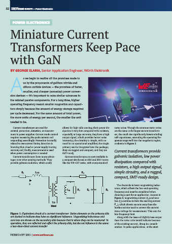
Figure 1: Equivalent circuit of a current transformer. Series elements on the primary side low-frequency limit.
S20 106
are dashed to indicate they have no significant influence. Magnetizing inductance and Along with the issue of slightly less output
core loss are shown on the secondary side because that is where they can be measured. In than the turns ratio would indicate because
operation, they are reflected and affect the primary side, but the net influence is the same: of the exciting current, droop is a consid-
a less-than-ideal current transfer. eration. In pulse applications, at the start
FEBRUARY 2021 | www.eetimes.eu