
Page 36 - PEN eBook February 2024
P. 36
DESIGN DESIGN
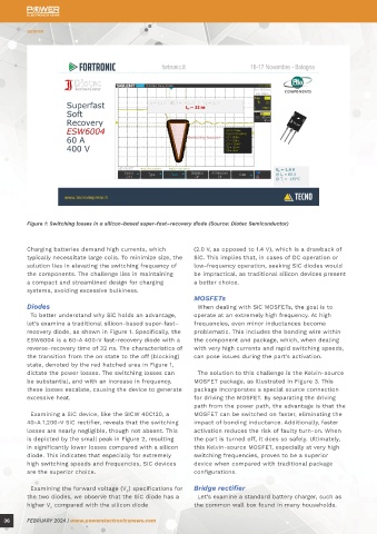
Figure 1: Switching losses in a silicon-based super-fast–recovery diode (Source: Diotec Semiconductor) Figure 2: Switching losses in a SiC-based diode (Source: Diotec Semiconductor)
Charging batteries demand high currents, which (2.0 V, as opposed to 1.4 V), which is a drawback of Although the wall box is nominally rated at 3 kW, recalculating, the overall power losses in the bridge
typically necessitate large coils. To minimize size, the SiC. This implies that, in cases of DC operation or the typical power consumption is 1 kW. A key are reduced to 6.7 W. Considering the widespread use
solution lies in elevating the switching frequency of low-frequency operation, seeking SiC diodes would component of the wall box is the bridge rectifier. of such wall boxes in our homes, the total available
the components. The challenge lies in maintaining be impractical, as traditional silicon devices present When using a GBU10K component in a 1-kW charger, market is currently about 120 million units. Assuming
a compact and streamlined design for charging a better choice. it draws approximately 4 A from the mains. With a that 10% of these wall boxes are equipped with the
systems, avoiding excessive bulkiness. voltage drop of 0.98 V per diode and only two diodes new low-power bridge rectifier, our calculations
MOSFETs conducting per half-wave, calculations show a power reveal potential energy savings of approximately
Diodes When dealing with SiC MOSFETs, the goal is to loss of 7.8 W in the bridge. 58 million kilowatt-hours worldwide, simply by
To better understand why SiC holds an advantage, operate at an extremely high frequency. At high adopting a different bridge rectifier. This is quite an
let’s examine a traditional silicon-based super-fast– frequencies, even minor inductances become Diotec has introduced a new bridge rectifier, the impressive result, and we are just talking about a
recovery diode, as shown in Figure 1. Specifically, the problematic. This includes the bonding wire within GBU10K-LV, featuring a lower V of 0.87 V. After single rectifier bridge.
F
ESW6004 is a 60-A 400-V fast-recovery diode with a the component and package, which, when dealing
reverse-recovery time of 32 ns. The characteristics of with very high currents and rapid switching speeds,
the transition from the on state to the off (blocking) can pose issues during the part’s activation.
state, denoted by the red hatched area in Figure 1,
dictate the power losses. The switching losses can The solution to this challenge is the Kelvin-source
be substantial, and with an increase in frequency, MOSFET package, as illustrated in Figure 3. This
these losses escalate, causing the device to generate package incorporates a special source connection
excessive heat. for driving the MOSFET. By separating the driving
path from the power path, the advantage is that the
Examining a SiC device, like the SICW 40C120, a MOSFET can be switched on faster, eliminating the
40-A 1,200-V SiC rectifier, reveals that the switching impact of bonding inductance. Additionally, faster
losses are nearly negligible, though not absent. This activation reduces the risk of faulty turn-on. When
is depicted by the small peak in Figure 2, resulting the part is turned off, it does so safely. Ultimately,
in significantly lower losses compared with a silicon this Kelvin-source MOSFET, especially at very high
diode. This indicates that especially for extremely switching frequencies, proves to be a superior
high switching speeds and frequencies, SiC devices device when compared with traditional package
are the superior choice. configurations.
Examining the forward voltage (V ) specifications for Bridge rectifier
F
the two diodes, we observe that the SiC diode has a Let’s examine a standard battery charger, such as
higher V compared with the silicon diode the common wall box found in many households.
F
36 FEBRUARY 2024 | www.powerelectronicsnews.com FEBRUARY 2024 | www.powerelectronicsnews.com 37