
Page 26 - PEN eBook May 2023
P. 26
SEMICONDUCTORS SEMICONDUCTORS
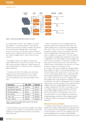
Figure 1: Solar panel application (Source: onsemi)
or a hybrid IGBT [Si IGBT + SiC diode] or a full-SiC “Level 1 is typically 120 V AC, is single-phase and
[SiC MOSFET + SiC diode] solution. While hybrid typically comes from a household outlet with max Figure 2: EV charging station block diagram (Source: onsemi)
solutions have become common already, SiC-based current rating of 15–20 A and very slow charge rate,”
full solutions will challenge them as SiC wafer Sattu said. “Level 2 is 220 V AC, is available at home,
costs reduce in the coming years. Assume that the workplace or public locations and adds 12–80 miles The gate oxide and ways to shield it from high electric WBG semiconductors have a lot of potential, but
system-level conditions are 500 V/25 A, F of 16 kHz per hour, depending on the power output level. fields remain a key focus area in device development. designers need to be aware of the difficulties that
sw
and output voltage of 800 V with a 600-µH boost Level 2 chargers can deliver up to 7.7–11 kW, making Improved screening tests are also important to filter come with using these materials. It is feasible to
inductor.” them capable of charging the average EV in about two out die that may have parametric drifts over time. accomplish a size reduction of passive components
to eight hours. The much larger DC quick chargers are (inductors and capacitors) and to create lighter and
According to Sattu, from Table 1, comparing a Level 3 and only available at commercial locations that The gate-oxide defect density must be kept to a smaller systems by operating at greater switching
hybrid-IGBT solution and full-SiC solution, it’s clear have access to three-phase power from their local minimum during processing to make SiC MOSFETs frequencies and at higher power densities. However,
that under the same conditions, overall losses are utility provider. These systems can add up to 100 miles as dependable as their Si counterparts. Innovative it can be challenging to predict how these smaller
significantly better in a full-SiC solution, resulting in or more of range to an EV battery in just screening methods must also be created to find and passive components would behave while operating
better efficiency. 30 minutes. Let’s look at a typical EV charging station remove possibly weak devices, such as in the electrical at higher frequencies, and heat management
block diagram in Figure 2. Let’s take the example of a end test. concerns may occur. Because they function at greater
“However, with SiC full modules, the switching DC fast charger at the system level. On the front end, temperatures than those supported by Si-based
frequencies can be increased 40 kHz or higher, there is a three-phase power-factor–correction [PFC] “At onsemi, we consider gate-oxide reliability in devices, WBG semiconductors require careful design.
resulting in the boost inductor to be as low as boost stage, implemented in a variety of topologies, numerous ways—intrinsic and extrinsic,” Sattu said. Greater thermal stresses are taken into account
200 µH, resulting in lower cost and weight,” Sattu such as two-level, three-level, uni- or bidirectional. “First, our EliteSiC process flow has been robustized throughout the design phase, which may negatively
said. The voltage levels from the grid 400 [EU]/480 [U.S.] are to include screening measure at various process steps impact the system’s dependability. Reproducing or
boosted up to 700–1,000 V. A subsequent DC/DC isolated to screen out possible process-induced failure modes. simulating harsh working circumstances in which
stage converts the bus voltage into the required output Second, we also implement either a wafer-level or electronic devices are subjected to extreme thermal
Parameter PIM-IGBT PIM-SiC voltage. The output voltage aligns with EV battery package-level burn-in methodology to eliminate early-life stress is one of the major problems for electronic
Conduction Loss 13.33 W 12.17 W voltages, typically 400 V or 800 V, and needs to cover failures. In addition, as part of an intrinsic reliability designers.
Switching Frequency 16 kHz 16 kHz the voltage charging profiles. Therefore, the DC/DC study, we evaluate our EliteSiC MOSFET technologies
The goal of thermal management is to effectively
Turn On Loss E on 3.8 W 3.17 W output range might swing from 150 V up to 1,500 V. under time-dependent dielectric-breakdown remove heat from the die and packaging. According to
characterization to ensure devices operate beyond
The value proposition of SiC MOSFETs comes into
Turn Off E off 34.66 W 3.06 W the picture here. To accommodate the bidirectional what is required from application profiles. Obviously, Sattu, there are few avenues to do so.
Total Loss 51.79 W 18.39 W charge/discharge process and wide voltage range of the tradeoff between oxide thickness and channel
T (T = 95°C) 137.9°C 109.9°C EV batteries, IGBTs are replaced with SiC MOSFET mobility limits what oxide thicknesses are used and the “First, by implementing a Cu [copper] baseplate
j c
solutions.” V (15 V or 18 V) applied in the application, determining option to improve the R from device junction to the
th
GS
Table 1: Comparing a hybrid-IGBT solution and full-SiC the long-term reliability.” heatsink—this is very crucial, especially for the EliteSiC
solution (Source: onsemi) DESIGN CHALLENGES M3 technology platform, which has the industry-leading
A number of basic long-term effectiveness concerns Figure 3 compares lifespan performance at V , specific on-resistance,” Sattu said. “As such, the die
GS
The second key focus area is EV chargers. According based on SiC quality, dependability and supply arise as which is substantially greater than what is employed is small, and by utilizing a Cu baseplate, the effective
to Sattu, the EV chargers of today fall into three main an increasing number of designers are presently using in practical applications. According to Sattu, it is heat-spreading area will be larger and result in lower
categories, separated mainly by their voltage input or have previously used SiC in their designs. With the obvious that it would go well beyond any industrial or thermal resistance. While offering a Cu baseplate is
and power level. commercialization and evolution of SiC MOSFETs, automotive use cases to obtain appropriate levels of not typical in industrial applications, onsemi offers this
gate-oxide reliability has improved significantly as well. failures under operational settings. option for F5 and Q2 power integrated modules [PIMs]
26 MAY 2023 | www.powerelectronicsnews.com MAY 2023 | www.powerelectronicsnews.com 27