Page 12 - PEN eBook October 2022
P. 12

DESIGN                                                                                                                                                                                                         Design


                                                                                                                                   is essential  for designing  the shape and structure of  the coils and  for predicting  which parts
                                                                                                                                   of the system will produce more heat during the charge. The software model will represent all
                                                                                                                                   power losses as power dissipated by resistors belonging to the modeled circuit. The results of the

                                                                                                                                   proposed approach have been validated by comparing the predicted loss with the measurements
                                                                                                                                   conducted on a 10-W WPT system, considering both alignment and misalignment condition of the
                                                                                                                                   coils. Read the original article here.


                                                                                                                                   The  block  diagram  of  a  classical  WPT  system  for  phone-battery  charging  is  shown  in  Figure  1.
                                                                                                                                   The transmitter includes the DC/AC inverter and the TX coil, whereas the receiver includes the RX
                                                                                                                                   coil, the AC/DC rectifier, and other conversion systems for the battery charger. Capacitors C  and
                                                                                                                                                                                                                              rTX
                                                                                                                                   C  maximize the power transfer in the range of the switching frequency by introducing a negative
                                                                                                                                     rRX
                                                                                                                                   reactance. The intermediate voltage V   is usually regulated through a low-bandwidth control loop,
                                                                                                                                                                        mid
                                                                                                                                   which wirelessly transmits the feedback  signal to the transmitter. This,  in turn,  can  adjust the
                                                                                                                                   target voltage by changing the switching frequency or the phase shift of the TX full-bridge. In this
                                                                                                                                   circuit, losses are mainly due to the copper and core losses of the TX and RX coils.


            A Software-Based


            Approach to Wireless


            Power Transfer


            Modeling


            By Stefano Lovati, technical writer for EEWeb                                                                          Figure 1: Block diagram of a wireless phone charger


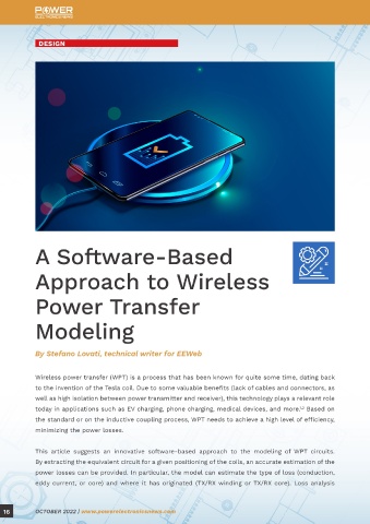
            Wireless power transfer (WPT) is a process that has been known for quite some time, dating back
            to the invention of the Tesla coil. Due to some valuable benefits (lack of cables and connectors, as                   CIRCUIT MODEL
            well as high isolation between power transmitter and receiver), this technology plays a relevant role                  The following relations describe the voltage and current characteristics of the transmitting and
            today in applications such as EV charging, phone charging, medical devices, and more.  Based on                        receiving coils:
                                                                                                 1,2
            the standard or on the inductive coupling process, WPT needs to achieve a high level of efficiency,
            minimizing the power losses.


            This  article  suggests  an  innovative  software-based  approach  to  the  modeling  of  WPT  circuits.
            By extracting the equivalent circuit for a given positioning of the coils, an accurate estimation of the               Where:
            power losses can be provided. In particular, the model can estimate the type of loss (conduction,
            eddy current, or core) and where it has originated (TX/RX winding or TX/RX core). Loss analysis


  16        OCTOBER 2022 | www.powerelectronicsnews.com                                                                                                                                OCTOBER 2022 | www.powerelectronicsnews.com          17
   7   8   9   10   11   12   13   14   15   16   17