
Page 27 - PEN eBook February 2024
P. 27
DESIGN DESIGN
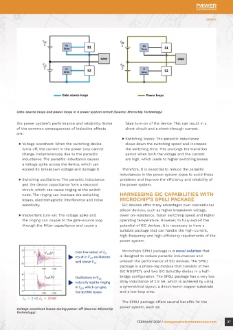
Gate-source loops and power loops in a power system circuit (Source: Microchip Technology)
Optimizing Power the power system’s performance and reliability. Some false turn-on of the device. This can result in a
of the common consequences of inductive effects
short-circuit and a shoot-through current.
System Loops: are: ▶ Switching losses: The parasitic inductance
▶
slows down the switching speed and increases
Voltage overshoot: When the switching device
Understanding the turns off, the current in the power loop cannot the switching time. This prolongs the transition
period when both the voltage and the current
change instantaneously due to the parasitic
inductance. The parasitic inductance causes
are high, which leads to higher switching losses.
Impact of Gate-Source and a voltage spike across the device, which can inductances in the power system loops to avoid these
Therefore, it is essential to reduce the parasitic
exceed its breakdown voltage and damage it.
Power Loops ▶ Switching oscillations: The parasitic inductance problems and improve the efficiency and reliability of
and the device capacitance form a resonant
the power system.
circuit, which can cause ringing at the switch
node. The ringing can increase the switching HARNESSING SiC CAPABILITIES WITH
By Saumitra Jagdale, contributing writer for Power Electronics News losses, electromagnetic interference and noise MICROCHIP’S SP6LI PACKAGE
sensitivity. SiC devices offer many advantages over conventional
silicon devices, such as higher breakdown voltage,
A power system is a complicated network of The loops in the electricity system are linked and ▶ Inadvertent turn-on: The voltage spike and lower on-resistance, faster switching speed and higher
electrical components that produce, transmit and impact one another. Both the power loop and the the ringing can couple to the gate-source loop operating temperature. However, to fully exploit the
distribute power to various loads. The gate-source gate-source loop influence how the device switches, through the Miller capacitance and cause a potential of SiC devices, it is necessary to have a
loop and the power loop are the two main loops and in the power system loops, parasitic inductances suitable package that can handle the high-current,
that make up a power system. The control circuit can lead to several issues, including switching high-frequency and high-efficiency requirements of the
that powers the switching device, such as an IGBT losses, accidental turn-ons, voltage overshoots and power system.
or silicon carbide MOSFET, is called the gate-source oscillations in the switching process. To reduce
loop. The gate driver, gate resistor, gate capacitance parasitic inductances and fully utilize SiC devices, it Microchip’s SP6LI package is a novel solution that
and gate inductance make up the gate-source loop, is crucial to improve the design and architecture of is designed to reduce parasitic inductances and
and the device’s performance and switching speed the power system loops. unleash the performance of SiC devices. The SP6LI
are set by the gate-source loop. package is a phase-leg module that consists of two
SOURCES AND CONSEQUENCES OF SiC MOSFETs and two SiC Schottky diodes in a half-
The primary circuit that transports the load’s voltage INDUCTIVE EFFECTS bridge configuration. The SP6LI package has a very low
and current is the power loop. This loop is made up In a power system loop, the inductive effects stray inductance of 2.9 nH, which is achieved by using
of the power source, the switching device, the load are caused by the parasitic inductances of the a symmetrical layout, a direct-bond–copper substrate
and parasitic elements like package inductance, PCB components and the layout. Parasitic inductances and a low loop area.
trace inductance and stray inductance. Therefore, are the unwanted inductances that are inherent in
the power system’s dependability and efficiency are any physical conductor. They are determined by the The SP6LI package offers several benefits for the
impacted by the power loop. geometry, length and proximity of the conductors. Voltage overshoot issues during power-off (Source: Microchip power system, such as:
Parasitic inductances can have negative impacts on Technology)
26 FEBRUARY 2024 | www.powerelectronicsnews.com FEBRUARY 2024 | www.powerelectronicsnews.com 27